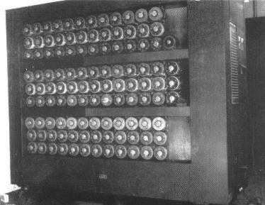
Although Turing is the father of the British bombe, the engineering, as distinct from logical, design of the bombe was due to Harold 'Doc' Keen an employee of The British Tabulating Machine Company at Letchworth which built the bombes under the Cantab trade-name. The bombe weighed about one ton, was housed in a bronze-coloured metal cabinet about 7 feet wide, 6 feet 6 inches tall and 2 feet deep and was mounted on castors. Protruding from the front of the cabinet there were 108 shafts (more in some models, fewer in the two prototypes) arranged in three 12 x 3 arrays on which drums were mounted.
See the above photograph of a British bombe and Figure 2.1, a diagram of the front panel of an idealised bombe.
 |
On the front panel of the bombe, around each shaft, there were 104 electrical contacts arranged in four concentric circles of 26 contacts each. The contacts associated with each vertical triplet of shafts formed a template of 312 contacts as indicated in the diagram to the left.
|
| These contacts were connected by wiring behind
the template as follows:
|
|
|
each contact in the
|
was connected to the corresponding contact in
|
|
outer (fourth) ring of the top set
|
a 26-way cable which could be plugged-up elsewhere in
the bombe
|
|
third ring of the top set
|
the outer ring of the middle set
|
|
third ring of the middle set
|
the outer ring of the bottom set
|
|
third ring of the bottom set
|
the second ring of the bottom set via wires which duplicated
the Umkehrwalze
|
|
inner ring of the bottom set
|
the second ring of the middle set
|
|
inner ring of the middle set
|
the second ring of the top set
|
|
inner ring of the top set
|
a 26-way cable which could be plugged-up elsewhere in
the bombe
|
Each vertical triplet of drums, the template they were mounted on, and the connecting wiring behind the template, constituted a double-ended scrambler. The task of each double-ended scrambler was to perform exactly the same transformation as that performed by the scrambler in the Enigma machine but unlike the single-ended Enigma scramblers, the bombe's scramblers had to be double-ended. For reasons that will appear later, it was necessary to connect a number of scramblers in series, that is, it was necessary to connect scrambler a to scrambler b, and scrambler b to scrambler g, without directly connecting scrambler a to scrambler g, but single-ended scramblers cannot be connected in this way.
Although each drum performed exactly the same transformation as its corresponding Enigma rotor, to enable the bombe's scramblers to be double-ended each drum had two sets of internal wiring each of which was configured to match the internal wiring of one of the rotors of the Enigma machine. For example, the drum corresponding to rotor IV of the Enigma would have 2 sets of internal wires, each set corresponding to the internal wiring in rotor IV. The task of the wiring in the drums was to bridge the contacts of the outer and third rings, and of the inner and second rings of contacts. Each double-ended scrambler was symmetrical, for example, if R was input at the left end of the scrambler resulting in F being output at the right end, then if R was input at the right end, F would be output at the left end.
Figure 2.2 shows the logical pathways through a double-ended scrambler.
The drums were approximately 5" in diameter and had 104 electrical brushes arranged in four concentric circles of 26 brushes each to match the contacts on the template. The operators had to take great care to ensure that the brushes did not short against each other. Each drum was coloured in accordance with the rotor that it replicated, so that, the drums would be coloured, say, red for rotor I, blue for rotor II, black for rotor III, and so on. All 26 letters of the alphabet were printed around the circumference of each drum so that an operator could readily determine its orientation.
Each of the three rows of double-ended scramblers formed a battery of scramblers. Each of the three batteries in the bombe was electrically isolated from the other two. So a bombe consists of three electrically isolated but mechanically connected batteries. Inside the bombe there was an electric motor which via a belt, a number of shafts, and an arrangement of gears, rotated the shafts, and their attached drums, in precise synchrony.
Copyright © Graham Ellsbury 1998
Continue to Part 3. How the Bombe was Plugged Up
Return to The Enigma and the Bombe main page